► Formula 1’s hybrid engines explained
► How so much power is eked out of 1.6
► And how e-power comes to the rescue
F1, they say is the pinnacle of motorsport, using the most advanced and expensive means to create the race car. Through its history F1 has used technology to boost the output from relatively small engines. For 2014 the FIA introduced a new breed of power unit into F1, hugely complex and notoriously hard to master. The current combustion engine and hybrid systems boast a 1000hp output but remain unpopular in some circles due to the lack of exhaust noise and costs. Perhaps these units are misunderstood, as they truly are incredible pieces of engineering.
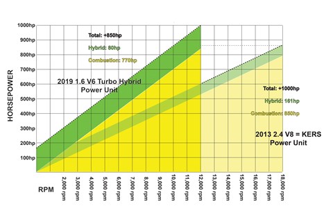
By the end of 2013, F1 cars were propelled by a 2.4l V8 engine with a simple hybrid system. A peak output of around 850hp was typical, although the engines were restricted in their technology, rpm and lifespan. As part of a reboot of F1 technology they were replaced with a totally new breed of engine.
Hybrid cars: further reading
The current engine formula is in service until at least until 2022. In summary, there’s a small internal combustion engine – a 1600cc V6 that’s turbocharged and features direct fuel injection. While this might be a recipe for a return to the eighties high boost 1500hp engines, the engine is instead capped by a fuel flow meter and the giddy heights of the mid-2000s 20,000rpm V8s is kept at bay by the fuel flow limit and a max rev limit of just 15,000rpm.
Allied to the combustion engine are two hybrid systems, one recovered kinetic energy of the car under braking (ERS-K) and another recovers the kinetic energy of the turbo charger, although in typical confusing F1 parlance, this is a heat recovery and the moniker applied is H for eat, so this is termed ERS-H.
Combined, these technologies allow an F1 driver to have around 1000hp at the pedal whenever it’s needed around a lap, with a little extra available for qualifying. Despite this huge output the race car burns just 110kg of fuel in the race (less than 135 litres), a third less than with the last of the V8’s.
In terms of power, the ERS system is capped at 161hp (120kw), so the V6 engine then produces nearly 850hp despite its lean fuel supply.
Formula 1 combustion technology
The obvious way to make power with a race engine is to rev as high as possible, if not then run lots of boost. However, the 2014 PU rules were written to prevent just these sorts of techniques, by applying a fuel flow regulation. There simply isn’t the fuel available to the engine to spin past 12,500 rpm or allow huge amount of boost.
For 2014 the manufacturers had to work out how to make the engine produce power with a paucity of fuel. What’s more the chemical make-up of the fuel was also restricted, so simply making rocket fuel, as was so successful with the early eighties turbos, was not possible either. Running lean means the engine is on the verge of knock, running too lean will eventually break the engine. Most manufacturers played with legal additives to reduce this effect, one of which being Ferrocene, an iron-based compound that literally made the insides of the exhaust pipe look rust red.
Mercedes, meanwhile, had found a little silver bullet: pre-chamber ignition. In a normal combustion chamber the spark plug ignites the fuel\air mix and the flame created spreads outwards to the edge of the chamber burning all the fuel air mix in the process. This is fine when there is enough fuel to mix in the right ratio throughout the combustion chamber. When there isn’t its hard to get full combustion.
Mercedes trick splits the fuel/air mix into two places; the main combustion chamber has a weak fuel/air mix, but a richer mix is held within a small chamber around the spark plug. With this pre-chamber set up, the plug ignites the rich mix. As this expands, it’s directed through small orifices between the pre-chamber and into the combustion chamber below, these jets of flame fully ignite even the weak mix for full combustion.
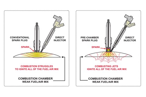
With this pre-chamber technology Mercedes had the jump on the opposition in 2014, it took time for their rivals to catch up and they have held the upper hand all the way to 2019.
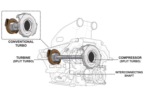
In terms of packaging the combustion engine, turbo and hybrid systems, there are two basic layouts. Already the rules define the engine’s mounting bolt positions, ‘V’ angle and max piston size and spacing. Restricted by the basic architecture of the engine, only the freedom of the packaging of a single turbo above the engine and along its centreline was available. It made sense to package the turbo at the rear of the engine, keeping the turbine’s heat away from the inlet plenum and fuel tank area at the front of the engine. Although this did give some headaches for routing the cooling pipes from the compressor to the intercooler in the sidepod.
Taking a non-conventional approach was Mercedes’ mantra, so they developed a unique set up. Wanting a compact intercooler installation of a front mounted turbo and the reduced thermal impact of a rear mounted turbo, they used both. The conventional turbo assembly is split, the hot exhaust driven turbine at the back of the engine and the cooler compressor at the front near the sidepods. The two parts joined by a long shaft running through the ‘V’ of the engine. This shaft would be the key reason for not taking this approach, the difference in speeding up and down of the two separate units, creates huge torsional loads in the connecting shaft. This meant either the shaft was very stiff and heavy to transfer the loads. The route Mercedes took was to run a flexible shaft, the twist along its axis taking up the difference in the inertia of the two impellers. Renault and Ferrari started and retained conventional rear mounted turbos, while Honda joined with a solution more like Mercedes, later developing into something much closer to the initial Mercedes split turbo design.
Along with turbo placement, charge air cooling is split between the teams. As the turbo compressor pressurises the air, the air heats up. Teams will want cooler denser air going into the combustion chamber, so the air will need to pass through a heat exchanger to cool it. For this an intercooler is used, two types are employed in F1. Most people will recognise the air-to-air intercooler, working just like a radiator the hot compressed air inside the core is cooled by colder ambient air passing outside. These are simple and light but do take a lot of space up within the sidepods, which is bad for the all important aerodynamics of the car. A few teams have run a different type of intercooler, a water-to-air type. Now the compressed air inside the core is cooled by water outside. This gives slightly less cooling, but is more consistent, as its less affected by the cars speed (as there’s less air passing through the sidepod) especially at the critical moments before the race start. However, the water in the jacket around the intercooler needs cooling in a separate water radiator. This makes for a heavier and more complex set up, but the water radiator takes less sidepod space, so it’s an aero gain over the air-to-air set up.
Only Ferrari and Mercedes have continually employed the water to air system, albeit Lotus did run the set up for one year in 2014. Their greatest rival, Red Bull, is able to maintain a tiny sidepod despite a large air-to-air intercooler in each sidepod.
With the right: fuel blend, combustion technique, packaging and cooling, the engine puts out some 530hp per litre. Even with less fuel flow and cubic capacity, the current combustion engine creates more horsepower than the old V8 engines it replaced.
F1 hybrid technology
Having two hybrid systems on the car, makes for most of the complication in the current power unit. Although broken down it is simpler to understand, based on the same tech as hybrid/electric road cars and even similar to toy remote control cars. There’s a Battery (ES-Energy Store), Motor Generator Unit (MGU) and Control Electronics (CE) to link the two.
MGU is a permanent-magnet brushless AC electric motor. It will both power the car as it deploys the stored energy, or it can work as a generator to put energy back into the battery. The battery is a pack of Li-ion cells, that are capable of rapidly deploying or storing lots of energy to the MGU. In between these two is the Control Electronic unit, which converts the AC electric of the MGU to the DC of the battery.
Cycling the electricity through each of these devices creates heat so each element requires liquid cooling – the FIA mandated dielectric fluid for the battery – to prevent risk of electric shock should it be damaged, while the more efficient water/glycol is typically used for the MGU and CE. So, both cooling systems need pumps and radiators to be packaged within the engine bay.
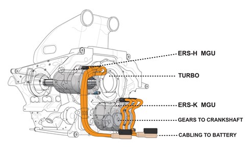
Given the same basic architecture, the two hybrid systems operate quite differently. Taking the simpler ERS-K first. The MGU is geared to the front of the engine’s crankshaft, in this position the unit can both drive and be driven by the engine. When deploying energy, the electric from the battery passes through the CE and into the MGU. This applies 161hp through the drivetrain to help accelerate the car.
Lessons from this greater power application have been learnt since 2014. In early testing in the power unit’s first year saw problems with the shafts and gears breaking under the sudden torque release from the MGU. Since then the manufacturers have found gentler ways to apply the torque and created a twisting shaft between MGU and the engine to absorb the spikes in power delivery.
In its reverse application the ERS-K recovers energy under braking. As the driver brakes, the ECU software switches the MGU into generator mode, which sees the MGU spun by the drivetrain and in doing so creates and sends electricity to the battery. The drag this generating creates ‘brakes’ the drivetrain, to the extent where the rear brakes are hardly used at lower speeds.
Rules restrict the potential of the ERS-K. In motor mode it can only deliver the 161hp, while the generator mode can only save 2mJ of energy to the battery. This means the motor only has the energy for about 33s of boost around a lap. Although you can store up to 4mJ of energy in the battery, so a lap’s worth of recovery can be saved and deployed as a double boost on one lap.
If ERS-K can be understood for its simpler motor and generator modes, the ERS-H is far more complex. This is another MGU and CE set-up, but it connects to both the battery and the MGU-K directly. However, the motor is connected directly to the turbo, thus the unit spins at up to 125,000rpm (the max rpm for the turbo), a huge engineering challenge in itself.
As a motor, the MGU can help spin the turbo, but not to create boost when on throttle, as if it were an electric supercharger. Instead the motor can keep the turbo rpm high when off throttle to act as an Anti Lag System (ALS). Doing this takes energy from the battery, taking it away from other potential uses, but given the lack of fuel available, this is still attractive, as normal fuel hungry ALS strategies burn fuel in the exhaust to keep the turbo spinning.
In generator mode the ERS-H can be used in several ways; some simple, others more complex and some probably still secret.
On a typical turbo, there is the problem of the turbo creating too much boost, as the exhaust pressure spins the turbo too fast at full throttle. This is controlled by an exhaust valve called a wastegate, that releases the exhaust pressure, reducing the turbo speed and dumping the excess exhaust gases into a separate exhaust pipe. This system works well but the energy in the exhaust gasses is wasted, so F1 allows the MGU to act in its generator mode slow the turbo, creating electricity as it does so.
Unlike the ERS-K there isn’t a cap of the amount of energy that can be recovered from the MGU. The battery will have capacity for both the 2mJ of the ERS-K and the ERS-H. So, the more they can use it, the more they can do other ‘motor’ tasks with the recovered energy. The obvious use for this is keeping the turbo spinning off throttle with the turbo MGU-H. But the rules allow the ERS-K to be powered from energy recovered from the Turbo. So, the more the teams can recover turbo energy, the more they can redirect it to the ERS-K and extend the 161hp boost.
Simply recovering energy from the turbo, whenever the wastegate effect would be needed isn’t enough. Most teams started 2014 (and for Honda’s debut in 2015) with turbo sized correctly for the engine’s conventional running. Again, it was Mercedes that realised that there was a gain to be had here. Even back in 2014, Mercedes ran a turbo compressor the size of a dinner plate on the front of its engine. An oversized turbo could be useful, even if it wasn’t needed for the extra ‘boost’ it created, but a larger turbo would need more open ‘wastegate’ time to prevent it over-boosting the engine. Thus, the MGU could be spun for longer periods and effectively gather more energy; even if the back-pressure effect of the turbo might hinder peak horsepower, the reusable energy gained could be used elsewhere around the track for faster lap times. One strategy used is at full power on the straights the energy recovered from the turbo is being routed directly at the MGU-K for the added 161hp boost.
In 2014 Ferrari missed this trick. It even had a wastegate designed with more through flow to reduce back pressure, thinking that combustion horsepower was more important than energy recovery. It soon reconsidered this strategy and for 2015 the wastegate and ERS-H strategy was far more like the Mercedes. Honda likewise missed the Mercedes strategy and re-entered F1 in 2015 with an engine designed to be very tightly packaged. The turbo was undersized in order to fit inside the ‘V’ of the engine, thus handicapping its ERS-H strategy. Honda, like most of the manufacturers, took time to mature the MGU-H design, the high RPM and heat stress it suffers made it one of the most difficult aspects of ERS to master.
This has reached the point where, at most tracks, the teams have enough deployable energy to use the 161hp boost for almost all of the lap where it can be used, way beyond the 33s ERS-K deployment.
This energy deployment is no longer a simple button on the steering wheel as used with the old KERS set up (2009-2013), instead the teams ECU software decides when to apply the ERS boost. The driver being able to switch between different maps that deliver ERS power with the pressing of the throttle pedal.
By having a regular output of over 1000hp, with its scant fuel supply and just three power units lasting a full season of over 20 races, they truly are the pinnacle of technology. Looking into the future F1 has a strategic decision on the split of combustion power to electric power. While unlikely to go fully electric in the foreseeable future, the end of the road for combustion engines might be in sight. F1, as it has always done, needs to reflect the changing world in which it lives. These current power units are step in the road towards the future.
Hybrid cars: further reading