► Formula E cars explained
► From battery to tyre
► What’s next for Formula E?
Formula E is quite new and also quite alien to many car and motorsport fans, so it’s useful to explain a little more about the series. It’s often assumed that Formula E is merely an electrified version of a conventional motorsport, and also that it’s a rival to F1.
Neither of these are in fact the case: Formula E set out to be very different from other single seater racing series; it didn’t have a legacy to follow, so all the norms and clichés of older race series have been avoided. It follows a single-make chassis and battery format, with the competitors encouraged to develop the hardware and software for the powertrain – thereby not wasting their resources elsewhere on the car.
Electric cars: further reading
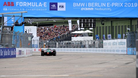
Instead, Formula E takes advantage of its clean and quiet format; the series exclusively runs in city-centres bringing the racing to the fans, rather than at some distant out of town race circuit – see most of the F1 calendar. It uses a one-day format to minimise disruption in the citym and many of its operational and logistical ideas are with sustainability in mind; for example everything is sea-freighted between races to sidestep the emissions of air-freight.
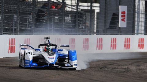
Inside BMW’s Formula E racer
The Michelin tyres are all-weather, so just one type of tyre is brought to each race; no wet weather tyres or alternative compound are shipped around the world, and this puts a cap on tyre performance – but th estreet-race one make format means this isn’t an issue. The series even brings its own power supply with generators providing charging power to the cars’ batteries with clean, renewable Glycerine fuel.
The street circuit format reflects well on the performance of the cars that are closer to F3 cars in power to weight ratio. A criticism often aimed at the series is when they’ll be at F1 levels of performance. Like all race series the ‘formula’ of regulations is designed to reflect the status of the series and the tracks its runs on, so Formula E will never go for power and weight that F1 runs to, given its city-centre format.
The story so far
While new, Formula E is now in its sixth season, starting back in Beijing in 2014. Over the intervening six years the category has gone through a lot of changes. In season 1, the cars were all identical; the chassis designed by Spark Racing Technology with Dallara as its technical partner was a spec design, as was the battery designed by Williams Advanced Engineering, the Hewland gearbox and the McLaren Applied Technology Motor/inverter/ECU.
All teams were only able to alter the car’s set up and develop the software that controlled the powertrain. For season 2 the powertrain was opened up for manufacturers to develop their own motor/inverter/gearbox set up. From a fully spec format the series immediately bloomed in a diverse technical formula, with many variations on the powertrain format; not all were successful, and few layouts continued to the latter seasons of the formula.
Through the first four seasons the battery capacity and powertrain output limited a car to only half the full race distance. Therefore, the driver had to swap to another identical but fully charged car mid-way through the race. While neither an attractive nor good example for electric car racing, this was a necessity, but would become a handicap to overcome with further development as the series progressed.
Formula E season guide
To manage costs, the spec chassis and battery are subject to a four-season tender process; we are thus part way through the second generation of car. Although every two years there is a makeover for both the chassis and battery specs, the evolution of the Gen 1 chassis brought the bi-plane nose wing and the Williams battery had internal updates. Then every season there are a few detail changes to the rules, either to improve the sport or cap loopholes found the previous season.
For season 5 there was the new Gen2 car, this was a totally new design, with aggressive looking bodywork, over a new chassis, that enclosed fresh battery design, now supplied by McLaren Applied Technology. For a similar size and weight, the new battery had double the energy storage and thus the awkward mid-race car swaps were abandoned and the driver races lights to flag with one car.
For season 8 there is an updated car, named the Gen2EVO, with revised bodywork. Then the third-generation car comes in, with more power and energy recovery systems that will prove to be yet another milestone in the series.
Powertrain
Most will be familiar with the powertrain of a combustion-engined race car, there is the; fuel tank, engine, gearbox and electronics looking after the ignition and injection systems. With an electric vehicle, the basic layout can be compared, but there is little the same between the two types. The Battery is analogous to the fuel tank, storing the energy for the motor. Albeit the battery is much heavier for the same energy storage as petrol, but also the battery does not get lighter as with a fuel tank during a race.
An electric motor is a swap for the combustion engine, in contrast to the battery, an electric motor is smaller and lighter than an equivalent engine. Plus it only has one moving part, therefore less bearings, friction and things to go wrong.
A genuine advantage is that the motor can also act as a generator, creating electrical energy under braking that can be stored in the battery. This is the equivalent to a combustion engine creating petrol to go back into the tank, something that is simply can’t do! As the one device can operate in both modes, the motor is often called a Motor Generator Unit or MGU for short.
What’s more, the motor produces full torque from zero rpm, rather than much higher RPM as on a combustion engine.
As these cars have such a strong torque output, the need for a multi ratio gearbox to multiply the torque is not required. Even in season 2 the Renault teams operated a car engaged in just one gear for much of the race, although a shorter first gear was available for the start and the slowest of hairpin corners. Now, no car runs a multispeed gearbox!
Without the need for fuel injection or ignition, the role of electronics on the electric race car are required to switch the electric from AC to DC between motor and battery respectively. In proper terminology this is called an Inverter/Rectifier, but is simply termed an Inverter in Formula E.
Under acceleration the battery provides energy through the inverter the power the motor, driving the rear wheels through a reduction gearbox and differential. Under braking, the Inverter switches and the motor generates electric, creating a drag on the drivetrain to help ‘brake’ the rear wheels. The electricity created goes to the battery and increases the remaining charge available to the driver through the race.
Battery
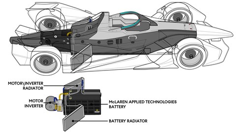
Literally central to the Formula E race car is the battery, as it’s at the core of the powertrain and is mounted in the middle of the car. Its commonly called the Battery, the Formula E nomenclature is RESS (Rechargeable Energy Storage System), while it’s also sometimes termed the ‘Traction’ battery, because it drives the car as opposed to the 12v auxiliary battery.
At home a battery what we call the little cylindrical object you put in your TV remote controls. In actual fact that’s a cell, a battery is basically a collection of cells. A Formula E battery is a collection of over 5000 cells! Inside the carbon casing made by McLaren Applied Technologies are separate modules, each housing a huge number of small AA sized cells made by Murata (Sony). By connecting the cells inside each module in series and parallel, then interconnecting the modules, the entire battery can produce 800v and a storage capacity of 54kwh.
This is twice the performance of the older Gen1 battery, the increase in energy storage allows the cars to race for the full +45 minute race without recharging or car swaps. The downside being the unit’s weight, there are 250kg of cells alone, plus the associated internal structure, connections, cooling and casing bring the battery up to over 400kg.

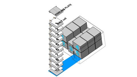
Back in season 1 Williams were given limited time to develop the first Formula E battery, its internal and external design was quite different to the current Gen2 unit. Firstly, the cell counts were much lower at 400, as Williams employed pouch type cells made by Xalt, which are about the size of an A4 padded envelope. These were stacked in three groups into modules, there being five modules mounted inside the battery case.
The benefit of the pouch format cell was that a cooling plate could be fitted in between each cell to cool both the pouch cell and the electric contacts. High spec batteries like these needs careful thermal management, there’s a temperature window they like to work within, not too cold as that affect efficiency and definitely not too hot. If a cell gets hot, then it can fail causing to get even hotter, a process called thermal runaway.
To prevent this happening, the battery has an electronic management system (BMS) to monitor each cell in terms of voltage, state of charge and temperature. Should cell temperatures get too high, the BMS will ‘derate’, which means it will warn the ECU to restrict power output to safeguard cell temperatures. If that fails, then it will tell the ECU to cut the motor, as a last safety measure to protect the cells.
The current McLaren battery is developed with Atieva as its specialist partner. It was their industry knowledge of all cell types commercially available that chose the Murata cell. While some believed that it was ‘cutting edge’ cell technology that lead to double of energy storage with the Gen2 battery, this wasn’t the case. The cell had been available before the Gen2 battery was developed and it was the way it was packaged and operated within the battery that made the difference.
Like the Williams battery the cells are densely packaged into modules stacked inside the battery case, but the electrical interconnections and cooling are very different due to the small cylindrical format of the cell. Rows of cells are offset from each other to pack them in tight, then there are cooling plates zig-zagging between the rows of cells to cool the cell bodies. From the outside these modules are then surrounded by the cooling pipework and manifolds, with electric bus bars to connect the modules into the single 800v DC output.
As the battery will remain live even if it’s been in a crash, the risk of electric shock to drive and marshals is very real. The casing is made from strong carbon fibre, with external Xylon anti-intrusion panels and internal insulating glass fibre layers. This structure gets crash tested and in the unlikely event of a breach to the outer casing, the cooling medium is dielectric fluid, which is an oil-based liquid, thus unable to conduct electricity, unlike water/glycol.
Motor
The technically inclined motoring fan will probably view an electric motor or generator, as the type of thing used as an alternator or starter motor on a road car. These are Brushed motors, where the magnetic stator is on the outside and the coiled armature spins inside. Carbon blocks (brushes) transfer the current between the stator and wiring, by literally rubbing against the contacts on the spinning armature, not a very efficient set up.
Modern motors reverse this design, permanent magnetic rotor now spins inside, while the coiled windings are formed in the body around it. Thus, the coils are stationary and no longer need the carbon brushes. Thus, these types of motor care called ‘brushless’.
Next the electric set up uses AC and not a DC supply, by running multiple pairs of magnets/coils (poles), to further enhance the efficiency of the set up. Given a DC power supply in the form of the battery, an inverter is required to create the requisite 3-phase AC output. In this this layout the motor generates torque twice from each pole as the AC switches from positive to negative, pulling and pushing the magnet around with each cycle.
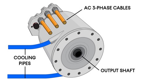
With the power cycling through the coils heat builds up and cooling is required to maintain the materials properties. Having the coils stationary rather than spinning makes this process easier and a coolant jacket passes water/glycol to take the heat away. A coolant circuit with an electric pump and radiator achieve this, the same system can also cool the Inverter package.
As detailed above, an electrical motor can create maximum torque from low RPM, although it can do this, there is a handicap. Low RPM/High torque outputs demand a lot of current from the battery, this becomes inefficient in an energy capped formula. So, the motors are run at higher RPM, where the torque may be less than at low RPM, but the electrical efficiency is far better. Each motor with have an efficiency curve, that maps torque to energy consumption, teams will aim to run the motor in the more efficient rev ranges for the race but may opt for the higher consumption lower rpm ranges for qualifying when energy consumption isn’t an issue.
Going for higher RPM creates efficiency benefits, but the limit becomes the ability to switch the electrical current at that rate and the material properties of the rotating parts. It’s the inverters job to create the electrical feed, to increase RPM and torque needs a step-in voltage and AC frequency. The latest Formula E battery runs at 800v and the converters run Silicon Carbide switches to allow this. While the spinning magnets will see higher centrifugal forces at higher RPM, the danger of the material and its joint to the rotor failing becomes the engineering issue here.
To make a motor more powerful, it becomes restrictive to make it larger in diameter as the tip speed of the magnets will increase, so the motor needs to be longer. For season 6 the motors are allowed to produce a maximum 250kw (in Qualifying) which is 335hp. Currently in Formula E most teams run a single motor, these are still tiny, 20-30cm in diameter and 30-40cm long, while weighing near to 20kg!
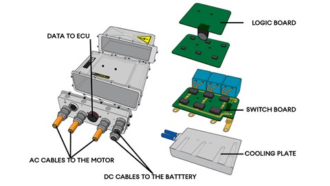
Inverter
It’s the job of the inverter to do all the electrical conversion from the DC of the battery to the high frequency high voltage AC for the Motor. This inverter/rectifier electrical function can be done simply with diodes, but for the level of performance required for an electrical vehicle, this requires something more complex, so the switching is achieved with semi-conductor technology
At its core the inverter has a power circuit-board, the two DC (battery) cables come in one side and the three AC (motor) cables the other. They pass via bus bars to these switches, which are controlled by a separate logic circuit-board, in order to translate the current from one form to another. The quicker the switches can switch, the more power they can handle and fewer electrical losses along the way the better the inverter’s performance will be.
For season 5 the new battery jumped from 400v to 800v and the motor’s output increased. But to step up in frequency and current requires different technologies, as the switches are capped by their material and operation. In addition, the current passing through the inverter’s switches creates heat. Again, the material properties of the switches themselves and the other circuit boards becomes a limiting factor.
The season 1 McLaren Applied Technology Inverter used Silicon switches known as IGBTs. These were fine for the performance back then, but as teams have switched to faster spinning motors and the increased operating voltage, Silicon IGBTs have their limits before they run too close to overheating. The alterative was to use the Silicon carbide (SiC) material, these switches are different internally to the Silicon versions and are technically termed MOSFETs.
They can switch more current as faster frequencies, while running hotter, therefore needing less cooling. By season 4 all teams were running SiC inverters, which had not just the performance benefits, but the inverters were much smaller and required a much smaller radiator in the sidepod to cool them, reducing aerodynamic drag.
While an inverter not requiring anything more than air cooling is a possibility, currently the switches and internal bus bars still require cooling, this is done with a cold-plate set up. The power circuit board is mounted against an aluminium plate with internal water-cooling passages, to conduct the heat away into the same cooling circuit as used for the motor.
Gearbox
Formula E mandates that power is fed from the motor to the wheels through a single differential, perhaps not the best way to operate electric motor final drive, but this has capped complex technology. This restricts torque vectoring, where power can be directed to each wheel, not simply to replicate a differential but to actively power/steer the car through the rear wheels.
This is potentially a huge performance advantage and is no doubt on the future technology road map for the series, but for now is rightly banned, so allow attention to be paid elsewhere in areas like energy recovery and electrical efficiency.
The season 1 and early season motors did not have the torque and efficiency curve to allow a ‘gearless’ set up. So, the motor was coupled to multispeed gearbox, 5 speeds in season 1, with teams reducing the number of gears as the motor performance\efficiency improved. Again, by season 4 all teams had removed multiple gears from their gearbox.
However, increasing motor RPM is well above the road speed of the wheels, so some reduction gearing still needs to be provided. Typically, the motor is connected to the differential via one or two reduction gears, the choice in the number depends of the size of the final drive ring gear around the differential. Some teams run a huge gear around the differential with just one reduction gear, others opting for a small ring gear but two reduction gears.
Detail development focuses on reducing driveline losses, areas such as: gear tooth design, friction reducing coatings, bearing design and low-friction seals. The entire gear package tends to be built into a machine aluminium outer casing to contain the gears, shafts, bearing and oil. This being a self-contained module, separate from the carbon outer casing that supports the suspension.
It’s worth remembering, that as electric motors do not idle but simply stop revolving, there is no need for a clutch. No Formula E car has run a clutch, and for some time none have gear shifts, so the driver starts and races with a twist-and-go set up.
Installation
From season 1’s standard powertrain installation to the variety of season 2’s set ups, the development path has converged again to the current near identical layout. By season 4 most teams adopted this transverse gear-less layout. Since the relatively relaxed early days, the level of secrecy in Formula E has grown exponentially with the appearance of the major manufacturers.
In recent seasons almost no pictures of the rear end casings let alone the powertrains hidden within have emerged. However, we do know a little of what might be going on at the back of the car.
The battery sits in its specified location, bolted up under the centre of the monocoque, in a conventional fuel tank-like position. This allows the battery to be protected from accident damage by both its own outer case and the survival cell around it. Holes in the monocoque allow access to the battery’s DC connection, ECU data connection and the cooling pipes. Being a spec part teams cannot modify the battery of gain access inside it. This can only be done by the McLaren staff that attend every test and race.
The teams can then design their own rear end to the car, the envelope that they are allowed to change reaches from the rear of the monocoque back to the rear crash structure and out to the rear suspension uprights. They can additionally fit their own cooling package in the left hand sidepod, as well as fit ECUs, control boxes and wiring around other parts of the car.
This rear end is formed around a carbon fibre casing, this houses the team’s own powertrain and connects the monocoque/crash structure/suspension. While the rest of the chassis is typical spec race car construction, the level of engineering shown in the team’s rear end set up is truly F1 spec technology. Strong, lightweight and full of finely engineered details.
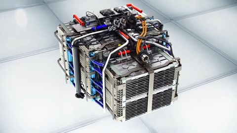
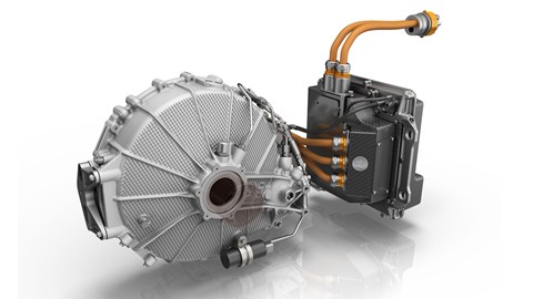
Inside the casing the teams mount the motor/inverter/gearbox package, this can only be removed when the complete rear end package is removed from the car. A generic set up consists of the motor mounted transversely at the front of the casing, this bolts to a gearbox package. Reduction gears from the motors output pinion, reduce the output RPM to road speed, increasing the torque as they do so. The final drive gear wraps around a differential to direct drive to the rear wheels. In this set up, there is not redirection of the motor’s output, i.e. no bevel gears. This reduces mechanical losses and side loading in the bearings, allowing for a lighter gear casing. The Inverter is either positioned above the motor or ahead of it, depending on the packaging of the gear set. Teams will want to reduce the Centre of Gravity height to improve handling, although front-to-rear weight distribution is set by the rules, so fore and aft positioning of the powertrain elements is of slightly less importance.
Connecting the units electrically is still often done with cables, two orange coloured cables coming from the battery connector to the inverter and three AC output cables then going into the motor. The use of cable and connectors is surprising, given the weight of these cables and the likelihood of faults leading to unreliability. It’s still common to package the units separately with these interconnections to give a little design freedom, rather than consolidate them into one unit.
The teams cooling package will feature an electrical water pump, driving the coolant through pipework to a small radiator in the left0hand sidepod. The size of this radiator gives strong clues to the efficiency of their powertrain. Heat being rejected from the inverter/motor means inefficiency, the best teams run tiny radiators.
The different approaches
That may be the basic design, but some team run different set ups, since the Gen2 car debuted in season 5 there have been two main variations that we know of, from BMW and Nissan.
BMW
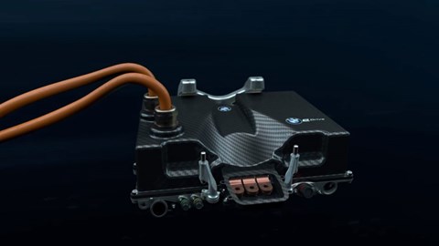
In formula E BMW have long been a partner of the Andretti team, the Bavarian engineers learnt from the experience and the season 5 powertrain differed in one key way from the generic transverse installation, in fact its literally turned the idea sideways. BMW decided to mount the motor lengthways inside the rear end casing, this requires a bevel gear get up to the final drive/differential. As the differential is mounted quite high at the rear, the motor is inclined to meet it. This angled installation allows space for the inverter to sit under the motor creating an exceptionally low and compact package.
Nissan
Nissan in season 5 were even more extreme. Nissan were new in FE in season 5, being formed from the Renault team that had pioneered the transverse gar-less layout with such success, but left the series at the end of season 4. Wanting to find a more performance within the tight rules and already having matured their conventional layout, they planned to stretch the rules and repackage the motor. Formula E being electric is able to restrict powertrain performance more effectively than with combustion-engined series. There is a clear and easily monitored cap on energy in and out of the battery, this caps electrical power and energy recovery. For teams the only gains on top of that are reduction in losses through the inverter, motor and gearbox. After four season s any sizable gains were hard to find, so where else could gains be? Nissan realised that the rules restrict electrical energy recovery, regenerative braking sends electricity back to the battery which gets measured, no sizable electrical storage is allowed outside the battery. But the rules are vague on kinetic energy recovery, so this was the route they are believed to have took.
As previously explained teams tend to run one motor, as that is all that is needed. Nissan’s solution is understood to have run two motors; one larger motor that does the major share of the torque production and a smaller one. This latter motor provides torque on acceleration, but also serves as an energy recovery device. Under acceleration, they work together, both driving the car forward geared to the same differential.
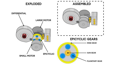
But as soon as the driver lifts off the throttle, the larger provides electrical regenerative braking to put energy back in the battery. Its then believed that the smaller motor rather than slowing with the rear wheels/differential is left to spin freely, conserving the kinetic energy built up on the straight. In this mode the smaller motor is acting like a flywheel, storing the energy built up on the straight. When the driver then accelerates the next time, the smaller motor releases the kinetic energy stored and drives the car forwards with additional torque.
How Nissan are alleged to have done this is quite imaginative, the rules only allow one differential to drive the rear wheels via the driveshafts and no clutch is allowed between a motor and drivetrain. So how does the smaller motor work independently of the larger one? Nissan used an epicyclic gear set between the two motors and the final drive. Epicyclics are commonly used in automatic gearboxes and host of other mechanical systems. One motor connects to the sun gear, the other to the planetary gears. With both motors driving the car forward, they work together to spin the ring gear and drive the car’s differential. As the car slows for the corner and the regenerative braking mode is engaged for the larger motor, the reverse torque of the motor provides the braking effect to the ring car to help slow the car (whilst generating electricity). Meanwhile, the smaller motor with neither power nor regenerative braking engaged, gets spun faster by the epicyclic gears, this builds up the kinetic energy in the motor. When reapplying the accelerator, the driver gets the electrical torque of the larger motor powered by the battery and also the torque stored up by the smaller motor, thus a double hit of power, greater than the electrical power alone!
While Formula E was initially quite open about its technology, teams freely stripping the car’s in the garages and exposing the powertrain, since the growth of the manufacturer leas teams, the secrecy has increased. It’s now hard to ever see what’s hidden within the rear carbon cases, let alone get a good photograph of one. Nissan kept its solution secret, indeed its still only speculation exactly how they did this. But soon, enough knowledge was discovered to make some guesses as to what is going on in the Nissan powertrain.
Other teams team felt this was outside the intention of the regulations and the spirit of the championship. Whereas F1 might be the piranha club, with only self-interest and no quarter given to competitors or the aim of the series. In Formula E there is more of a common aim and direction with the series and its teams. So, when issues like this arise, they tend to be sorted for the common interest. As a result, double motors and Epicyclics are now banned in Formula E and teams will need to look elsewhere for an advantage.
The future of Formula E
Formula E has a clear but pragmatic roadmap, working with its competitors to plan future technology into the rules. Although the schedule has been delayed by the Covid situation, in the Gen3 car there will be new battery and powertrain specification coming for season 9. The plan has been to increase power and lighten the cars, this will bring the car’s power to weight ratio above the current FIA F3 cars that support the F1 races. The battery will be lighter from a reduced capacity, but this loss in energy storage will be boosted by both greater rear axle regenerative braking, but also two new technologies’, firstly mid race recharging and secondly an energy recovery system linked to the front wheels. In this spec the car will not need rear disc brakes, the entire rear braking effort coming from regen braking alone. So, the Gen3 car will not have any rear disc brakes fitted!
Going further into the future, there will be an increase in power, while still understanding that the series races on tight street circuits so there is a ceiling on the maximum output for obvious safety reasons. There will also be undoubtedly an increase in regenerative braking means there may not be front disc brakes either. While, the front regen unit could be set up to provide four-wheel drive, perhaps the car going to an individual motor per wheel, allowing for torque vectoring for even greater performance. The pitstop recharging could be sped up or even extended to wireless induction charging from electrical cabling fitted along the straights. The sky is the limit, but all of these technologies will be reflected in the road car EV industry and will continue to make Formula E the tech great technology incubator it was set up to be.